
Kwikstage Base Jacks & Foundations: SWL Derating, Solid vs. Hollow Stems & Importer Sourcing Guide
Compare Kwikstage base jacks by certified extension ratings, stem design and foundation checks. Use the inspection checklist to prepare an evidence-backed RFQ.
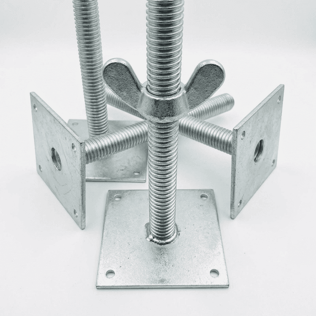
Kwikstage base jacks transfer scaffold leg reactions to the foundation while providing level adjustment. For importers, hire fleets and scaffold specifiers, the buying question is whether the exact jack and standard combination has a documented permissible leg load at the extension the project needs.
Scope and review date: October 26, 2026. This English guide supports global procurement comparisons. Australian and UK sources below explain their own jurisdictions; they do not establish approval in New Zealand, Europe, Southern Africa or another destination market. Confirm locally applicable requirements with the responsible designer.
Evidence boundary: no model-specific load report, physical test or customer case study is supplied here. The tables are document-review prompts and explicitly hypothetical arithmetic, not certified SWL curves, soil classifications or erection instructions. For each order, identify the manufacturer, model, drawing revision and intended scaffold configuration before accepting a capacity claim.
Coordinate base-jack quantities with your Kwikstage standards and ledgers and transoms. Ready to compare offers? Send your base-jack RFQ and required extension.
Quick sourcing answer
- Extension: compare the permitted leg load at the actual extension, not a single headline capacity. Reject an offer whose load basis or extension datum cannot be identified.
- Solid or hollow: select by documented duty and fit first, then measured finished weight, condition and delivered cost.
- Manufacture: specify the drawing, nut material, thread fit, weld acceptance and coating process; a material label or product photograph cannot certify the assembled jack.
- Foundation: check the ground or supporting structure separately. A jack rating cannot establish a soleboard or slab rating.
1. Extension, Buckling & SWL Derating
A longer unsupported stem can be more susceptible to buckling and bending. Ideal elastic column theory illustrates the length effect:
Here E is elastic modulus, I is the second moment of area of the relevant section, L is unsupported length and K represents end restraint; K × L is the effective length. For unchanged E, I and K, doubling L gives one quarter of the ideal elastic buckling load. This is a theoretical relationship, not a measured SWL reduction.
Actual limits can involve thread-root geometry, yielding, nut engagement, welds, eccentricity and the scaffold assembly. Do not turn Euler results or an ultimate test load into an allowable working load using an assumed safety factor. Ask for the stated rating basis and the manufacturer’s extension table. The HSE scaffold design guidance explains the role of recognised configurations, manufacturer instructions and competent design in the UK.
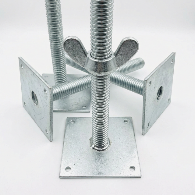
Use the following seven checks to compare supplier load schedules. A missing rating remains unknown; do not interpolate between models or beyond the supplier’s permitted range.
| Check point | Evidence required | Procurement decision |
|---|---|---|
| Minimum approved extension | Permissible leg load, extension datum and matching model drawing. | Use as a baseline only within the stated configuration. |
| Intermediate extension | Load schedule covering the intended site setting. | Use only the supplier’s approved selection or interpolation method. |
| Maximum approved extension | Limit marking, minimum insertion and permitted leg load at that limit. | Confirm the entire jack and standard combination is covered. |
| Beyond the approved range | A different approved component or a revised competent design. | Do not treat added bracing as automatic permission to overextend. |
| Eccentric or lateral loading | Test or calculation basis for the relevant eccentricity and restraint. | A concentric axial result alone is insufficient. |
| Base lift and restraint | Manufacturer’s arrangement for ledgers, transoms, bracing and ties. | Confirm the rating applies to the proposed assembly. |
| Report traceability | Model, tested configuration, laboratory, report number, date and rating basis. | Hold acceptance when a report cannot be matched to the offered product. |
Schematic: Kwikstage Base Jack Assembly & Extension
2. Solid Bar vs. Hollow Tube: Engineering Mechanics & Freight Economics
Neither construction type has a universal capacity advantage. Compare the offered jack, nut and plate assembly at equal required duty and extension, with the same compatibility and rating basis.
Hollow tube stems
A hollow stem can reduce finished-unit mass, depending on its dimensions and material. Request the wall thickness and tolerances after thread forming, and the internal corrosion-protection and drainage detail. Dents, distortion and damaged threads require assessment against the manufacturer’s rejection criteria.
Solid bar stems
A solid stem removes the internal cavity but may increase mass. It can still bend, corrode or suffer thread damage; it does not establish suitability for shoring or permission to reuse an impacted jack.
| Parameter | Solid stem | Hollow stem | Buyer action |
|---|---|---|---|
| Permitted leg load | Model-specific. | Model-specific. | Compare at the required extension and restraint. |
| Finished unit mass | Weigh the complete offered assembly. | Weigh the complete offered assembly. | Include nut, plate, finish and packing mass. |
| Section and thread geometry | Confirm root diameter and material. | Confirm root geometry and formed wall thickness. | Match drawing revision to the test evidence. |
| Damage inspection | Check bending, corrosion and thread condition. | Also check dents and wall deformation. | Use documented rejection criteria for both. |
| Coating and drainage | Confirm external coating and thread fit. | Also confirm internal protection and safe venting. | Agree the process and inspection requirements. |
| Standard compatibility | Confirm insertion, seating and permitted combinations. | Confirm insertion, seating and permitted combinations. | Check an actual mating sample; fit alone does not prove capacity. |
| Delivered cost | Use quoted mass and verified loading plan. | Use quoted mass and verified loading plan. | Compare equal-duty assemblies and total landed cost. |
Worked freight example — hypothetical inputs
Assume a verified goods-mass allowance of 20,000 kg after reserving packing mass, and finished jack masses of 5.2 kg and 3.4 kg. The mass-only ceilings are floor(20,000 / 5.2) = 3,846 solid jacks and floor(20,000 / 3.4) = 5,882 hollow jacks. The hypothetical lighter unit is 34.6% lighter; it permits 2,036 additional pieces by mass alone.
These are arithmetic ceilings, not measured product weights or a container loading promise. Confirm the container’s actual payload, packing volume, floor loading, load distribution and route limits. Actual pieces per shipment can be lower. For an equal container freight charge F, compare F divided by the verified loaded quantity. Request finished-unit weights and a packing proposal before comparing freight per delivered jack.
3. Component Anatomy & Manufacturing Metallurgy: Rolled Threads, Ductile Iron Nuts & Baseplate Welds
Specify the stem, nut and plate as a matched assembly. Require the supplier to identify the controlling drawing and inspection plan rather than accepting an unsupported claim of compliance with several standards.
Thread form and finished fit
State the approved thread profile, pitch, tolerances, engagement and manufacturing route. Rolled and machined threads require suitable process control; neither a process name nor a photograph proves fatigue performance. Test finished sample fit after coating without forced adjustment or unauthorized thread cutting.
Nut material and acceptance
Ask for the specified grade, applicable material standard and batch documentation. Ductile and grey iron have different properties, but grade names from different standards are not automatically equivalent. Low-temperature performance requires its own evidence. Do not use an improvised hammer test or adjust a loaded jack without an approved procedure.
Plate, weld and coating
Obtain plate dimensions, weld size and weld acceptance criteria from the approved drawing. Fillet-weld leg length and effective throat are different dimensions; this guide prescribes neither. Agree any visual, dimensional and additional inspection with the responsible supplier or engineer. Specify coating acceptance for the actual process, material thickness and threaded parts; a universal micrometre target is unsuitable.
4. Geotechnical Interface: Soleboard Sizing & Ground Pressure Calculations
Check the foundation independently of the jack’s rating. For a hypothetical 150 mm × 150 mm plate carrying a 30 kN leg reaction, the average contact pressure is:
This arithmetic does not establish soil failure or slab adequacy. A designer must establish ground or structural capacity, settlement, voids, drainage and load spreading. Concrete strength alone does not establish a suspended slab’s capacity for a concentrated leg load. The HSE foundation guidance calls for firm, level support capable of carrying the scaffold and its loads.
| Assumed allowable pressure | Arithmetic area P / q | Equivalent length at 225 mm width |
|---|---|---|
| 50 kPa | 0.600 m² | 2.667 m |
| 75 kPa | 0.400 m² | 1.778 m |
| 100 kPa | 0.300 m² | 1.333 m |
| 150 kPa | 0.200 m² | 0.889 m |
| 200 kPa | 0.150 m² | 0.667 m |
| 300 kPa | 0.100 m² | 0.444 m |
Method: divide 30 kN by the assumed allowable pressure in kPa to obtain area in m²; divide that area by 0.225 m for equivalent length. These inputs are not assigned to soil types and are not foundation approvals. They assume one leg, uniform contact and full effective load spreading.
At the hypothetical 100 kPa value, a 225 mm × 1,500 mm board has a gross area of 0.3375 m², giving 30 / 0.3375 = 88.9 kPa if all of that area is effective. Board bending, shear, bearing, thickness and support still require design. If two 30 kN legs share a board, the applied reaction is 60 kN; the one-leg result cannot be reused unchanged. Secure base plates only as required by the approved arrangement.
5. Slopes, Swivel Jacks & Eccentric Loading Boundaries
Keep the jack aligned and its plate fully supported in the approved foundation arrangement. Do not assume a flat plate can accept a particular ground slope, or use loose packing to correct it without an approved detail.
- Fixed base: obtain the permitted foundation and levelling arrangement from the system instructions.
- Swivel base: obtain the exact model’s permitted angle, extension, load schedule, retention and restraint requirements. A swivel alone does not prevent sliding or establish slope stability.
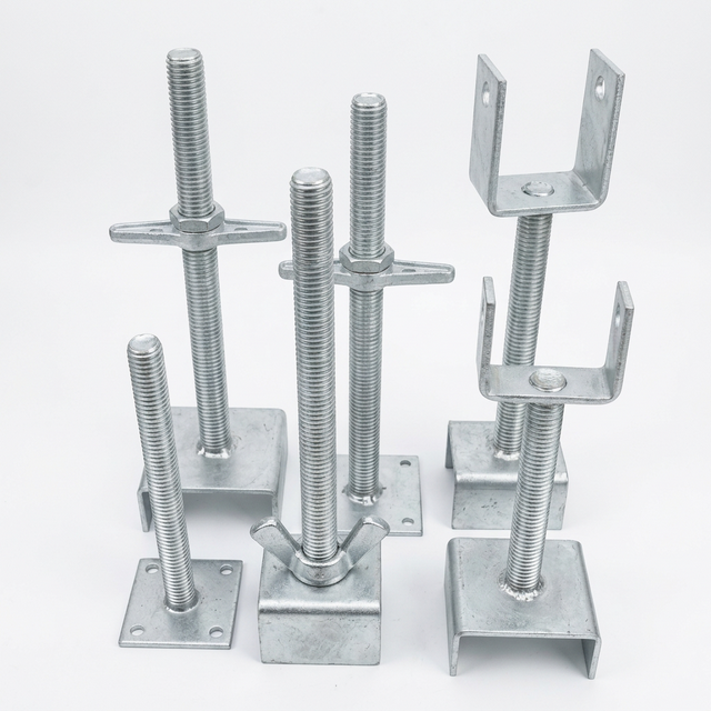
- U-head: treat it as a different support component with its own intended position, load path and approved application. Do not substitute it for a ground base on appearance alone.
6. Importer QC & Factory Receiving Inspection Checklist
Agree sampling, acceptance limits, inspection responsibility and handling of nonconforming pieces in the purchase order. Use this checklist before shipment and on receipt; visual inspection cannot replace load evidence.
12-Point Purchase & Receiving Checklist
- Identity: record model, drawing revision, manufacturer and batch.
- Compatibility: check the specified standard, seating and permitted component combination.
- Section: measure stem dimensions and hollow-wall thickness against agreed tolerances.
- Condition: inspect straightness, corrosion, dents and thread damage using documented rejection criteria.
- Material: match stem, nut and plate grades to batch documentation and the order.
- Thread fit: check the unloaded finished sample over its permitted travel with the specified nut.
- Limits: confirm insertion, maximum extension, markings and any specified retention feature.
- Plate: verify dimensions, flatness and hole details against the drawing.
- Weld: inspect the specified weld dimensions and acceptance criteria; retain required records.
- Coating: verify the agreed process, coverage, thickness criteria and finished thread fit.
- Load evidence: match the report and permitted-load schedule to the supplied assembly and extension.
- Shipment: confirm counts, measured mass, packing plan and quarantine of nonconforming pieces.
7. Action Summary & Commercial Inquiry Guide
Shortlist only offers with compatible assemblies and a traceable rating basis. Then compare finish, inspection requirements, serviceability and actual packed shipment cost. For the RFQ, send the destination market, component quantities, required extension, design leg reaction, mating standard, finish and delivery schedule. Mark unknown design inputs as unresolved rather than substituting a generic SWL.
Request a Documented Base Jack Proposal
Send Kwikstage Direct your required configuration and ask for the proposed model drawing, available test evidence, material records and packing details. Confirm what documentation is available for the offered batch before purchase approval.
8. Questions Buyers Ask
- Why does extending a Kwikstage base jack reduce its load capacity?
- Extension increases the unsupported stem length and can increase buckling and bending demand. The percentage reduction is specific to the jack, thread-root section, restraint and scaffold configuration. Use the manufacturer’s permitted leg-load table at the actual extension; Euler buckling alone cannot establish a safe working load.
- Should an importer choose solid or hollow base jack stems?
- Compare models with documented ratings for the required extension and compatible standards first. Then compare measured finished-unit mass, corrosion protection, inspection criteria and delivered cost. Hollow construction may reduce mass, but neither a hollow nor a solid stem establishes load capacity or resistance to site damage by itself.
- What minimum insertion and maximum extension should be specified?
- Use the limits in the instructions and approved drawing for the exact jack and scaffold standard combination. Record the insertion measurement datum, maximum extension and retention arrangement in the purchase order. This guide does not establish a universal 150 mm overlap or 450 mm working limit.
- How should buyers check threads after galvanizing?
- Agree the coating and thread-fit requirements with the supplier. Check an unloaded finished sample through its permitted travel, using the specified mating nut and gauges where required. Reject binding, damaged threads or unauthorized rework. Coating appearance or a free-running nut alone does not prove strength or coating compliance.
- When should a swivel base jack be considered?
- Where a level, fully supported foundation cannot be achieved using the approved fixed-base arrangement, ask the scaffold designer whether a rated swivel assembly is suitable. Obtain its permitted angle, extension, load and restraint requirements. There is no universal 3-degree changeover, 45-degree operating permission or fixed percentage derating in this guide.
9. Sources & Verification Limits
Sources checked October 26, 2026. The standard’s catalogue establishes its identity and scope; the full clauses and model-specific test records were not reviewed. Regulatory guidance is jurisdiction-specific. None of these links certifies a supplied jack or validates the hypothetical freight and foundation examples above.
- Standards Australia — AS/NZS 1576.2:2016, Scaffolding, Part 2: Couplers and accessories. Official catalogue scope for procurement reference, not evidence of a universal jack load, overlap or weld dimension.
- Safe Work Australia — Scaffolds and scaffolding work general guide. Australian risk-management guidance; the publication page links the guide and identifies jurisdictional regulators. It is not itself a product approval or a global statutory specification.
- UK Health and Safety Executive — Scaffolds. Guidance on competent design, manufacturer instructions, foundations and inspection in the UK; it supplies no generic base-jack derating curve.
Recheck this guide before the next order, and whenever the product, report, standard edition or destination requirements change. For related procurement updates, return to Kwikstage buyer insights.