
Kwikstage Hop-Up Brackets: 1, 2 & 3-Board SWL, Eccentric Moments & Tie-Bar Sourcing Guide
Source Kwikstage hop-up brackets with model-specific SWL checks, 1–3-board comparisons, eccentric-load examples and tie-bar inspection steps. Plan your RFQ.
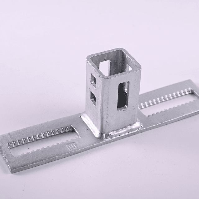
Kwikstage hop-up brackets, also called stage or cantilever brackets, extend the platform towards the building face. The first sourcing question is the Safe Working Load (SWL), but board count alone cannot answer it. A 1-board, 2-board, or 3-board description identifies a deck arrangement; it does not certify a load rating. Obtain the exact model’s load table and installation instructions before assigning workers, tools, or stored materials to the extension.
This guide is for scaffold buyers, hire-fleet managers, and temporary works teams comparing bracket-and-tie-bar packages. Its practical output is a purchase specification: what loading evidence to request, which dimensions to match, and which unresolved items should hold an order. It does not provide a rated design for any pictured product.
Scope and review date: November 5, 2026. Global sourcing guidance, with Australian and UK public safety sources identified below. Local regulations, current applicable standards, manufacturer manuals, and project design govern use. AS/NZS 1576 and EN 12811 references are not interchangeable product approvals. No physical load testing, factory audit, or independent product certification was performed for this guide.
Coordinate the bracket schedule with your Kwikstage standards, ledgers and transoms, and steel planks. Send the model, required quantity, and destination market to Request a hop-up bracket quotation and documentation review.
Quick Sourcing Summary: 5 Rules for Hop-Up Procurement
- Buy a documented arrangement: Match the bracket, deck, restraints, bay length, and permitted loading to one identified manufacturer configuration. List any proposed substitutions separately.
- Keep load units separate: A platform load per bay, a reaction per bracket, and a UDL in kN/m² describe different things. A point-load limit also needs its contact area and position.
- Schedule tie bars and retention: Include compatible anti-splay components and the installation detail. Do not delete them from a quotation without documented acceptance of the alternative.
- Review the complete scaffold: Eccentric bracket loads affect standards and stability. Main-deck loading and other working lifts remain part of that review.
- Agree inspection limits before manufacture: Use the approved drawing and inspection plan for welds, wedges, finish, and fit. A generic minimum dimension is not a substitute for that plan.
1. Hop-Up Configurations: 1-Board, 2-Board & 3-Board SWL
Start with actual plank width, bearing length, bracket projection, and connection geometry. As dimensional arithmetic only, one, two, and three nominal 225 mm boards total 225, 450, and 675 mm before gaps or clearances. These sums are neither pocket dimensions nor a regional manufacturing standard. Obtain finished dimensions after coating, and check whether the quoted projection is measured from the standard centreline or from its face.
1-Board Hop-Up Bracket: Check the Access Arrangement
A narrow extension can close a working gap alongside a main deck, but should not be assumed to be a standalone access platform. Record how the worker reaches it, where feet and tools will be placed, and how the plank is retained. Ask whether any permitted omission of a separate tie bar applies to this exact bracket-and-plank arrangement. Do not infer an exemption from the single-board name.
2-Board Hop-Up Bracket: Specify the Whole Assembly
With two boards, the buyer needs both the deck support detail and the tie-bar arrangement between adjacent brackets. Request the acceptable plank span, end support, restraint orientation, and loading pattern. Trades such as rendering or brickwork describe intended activities; they do not establish permission to place a mortar tub or stack of bricks on the extension. Include those proposed loads in the RFQ.
3-Board Hop-Up Bracket: Width Does Not Establish Heavy Duty
A wider extension can move the load further from the standard and can carry more total load at the same pressure. Both effects matter to the supporting frame. Obtain confirmation of the allowable combination of main platform and hop-up loading, the number of simultaneously loaded lifts, and any restrictions at corners or end bays. Do not scale a 1-board rating by three or label a 3-board assembly heavy duty without configuration-specific evidence.
2. Engineering Comparison: Hop-Up Specifications Matrix
Use this matrix to compare supplier submissions. The dimensions are illustrative board-width sums; every load and fit requirement must be completed from the selected model’s documentation. Australian duty labels and European load classes must not be assigned by board count.
| Parameter / Attribute | 1-Board Hop-Up Bracket | 2-Board Hop-Up Bracket | 3-Board Hop-Up Bracket |
|---|---|---|---|
| Illustrative Board-Width Sum | 225 mm total for one assumed 225 mm board | 450 mm total for two assumed 225 mm boards | 675 mm total for three assumed 225 mm boards |
| Duty / Load-Class Evidence | Confirm permitted extension use in the manual | Confirm the exact two-board configuration | No automatic heavy-duty classification |
| Concentrated Load / Bracket Reaction | Request point-load position and contact area | Request point-load limit and bracket reaction limit | Request reactions for end and intermediate brackets |
| Distributed Platform Load | Request the permitted UDL and applicable bay length | Confirm whether main-deck and extension loads combine | Confirm loading pattern and simultaneous loaded lifts |
| Eccentricity e for Design Review | Use actual load position and connection geometry | Use the centroid of the specified load pattern | Check local and overall effects; no fixed derating |
| Anti-Splay and Plank Retention | Follow the documented single-board arrangement | Include matching tie bars or an approved alternative | Include matching restraint and installation details |
| Edge Protection / Handrail Post | Confirm facade gap and fall-prevention arrangement | Confirm compatible posts and end protection | Confirm the approved post connection and barrier loads |
| Mass and Traceability | Request actual unit mass and model / batch identity | Include tie bars and retention parts in packing weights | Verify the supplied assembly against its drawing revision |
3. Eccentric Moments: A Reproducible Load-Path Example
A downward bracket reaction F acting at distance e from the standard centreline creates a moment M = F × e. This is a load-path calculation, not a capacity check. The designer still needs the connection behaviour, restraint conditions, member properties, imperfections, and combined loads to assess the scaffold. An anti-splay tie bar does not remove the eccentric vertical load or replace structural ties to the building.
Illustrative assumptions, not a product rating: Take two equal 2.4 m bays with a 0.69 m wide extension, a uniformly distributed live load q of 2.0 kN/m², and an assumed deck dead load of 0.30 kN per bay. Model each bay independently as simply supported between brackets. This deliberately simplified model excludes main-deck loads, impact, wind, guardrail loads, and construction load combinations.
Area per bay = 2.4 × 0.69 = 1.656 m²
Live load per bay = 2.0 × 1.656 = 3.312 kN
Total illustrative bay load = 3.312 + 0.30 = 3.612 kN
End reaction from one bay = 3.612 / 2 = 1.806 kN
Shared intermediate bracket = 1.806 + 1.806 = 3.612 kN
At assumed e = 0.40 m: M = 3.612 × 0.40 = 1.445 kN·m
The example shows why an intermediate bracket receiving load from two adjacent bays must not be assessed as though it supports only one bay end. Actual reactions change with deck continuity, uneven loading, geometry, and connection stiffness. The assumed eccentricity must also be replaced by the actual resultant load position, especially for a concentrated load near the outer edge.
Do not turn the resulting moment into a universal 25–40% reduction of standard capacity. Request a configuration check covering compression, bending, buckling, connections, ties, bracing, and foundations. The HSE scaffold design guidance requires manufacturer guidance for recognised system configurations and competent design when the arrangement falls outside that scope. A schematic cannot establish where a tie must be installed or its rating.
Structural Schematic: Cantilever Moment Vector & Tie-Bar Anti-Splay Restraint
Conceptual load-path illustration, not to scale. The wall tie and separate anti-splay detail show different functions; their positions, capacities, and installation must follow the approved design.
4. Tie-Bar Anti-Splay and Dislodgement: Buy the Installed Detail
The Queensland guidance on hop-up bracket tie bars addresses both splay and inadvertent detachment. It describes preferred straight-pin and bent-pin installations as well as unsafe examples. A 45-degree bend is therefore not a standalone compliance test. Plank position and bar orientation affect retention; follow the manufacturer’s documented arrangement and check resistance to unintended release.
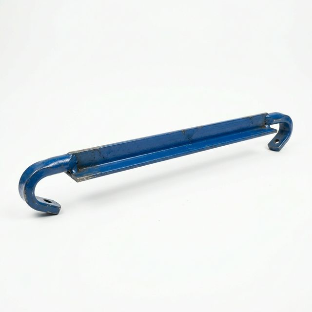
What to Request with the Tie-Bar Quotation
Specify bay centres, end engagement dimensions, orientation, and the parts that retain the planks. Obtain an assembled photograph or drawing, not just an isolated bar image. Ask the supplier to identify the manual page governing installation, removal, and inspection. For a revised design, record which old brackets and planks it can be used with and who accepted that combination.
Do not resolve a poor fit by enlarging holes, bending pins, grinding a wedge, or welding an extra lug on site without design approval. Such changes can alter both engagement and traceability. Keep incompatible samples separate from hire stock while the supplier resolves the discrepancy against the agreed drawing.
5. Factory Audit Checklist: 8 Quality Checkpoints for Importers
Turn these checkpoints into a purchase-order inspection plan. Each needs an approved reference, a sampling method, an acceptance criterion, and a named person authorised to release or reject the batch. These are buyer-side process recommendations, not universal dimensions mandated by a scaffolding standard.
- Model and drawing control: Record bracket and tie-bar part numbers, drawing revisions, manufacturing site, and the exact loaded assembly covered by the supporting report. A certificate for another bracket width or another factory does not close this check.
- Material traceability: Match the specified steel grade, section sizes, and material records to the production batch. Agree how substitutions are reviewed. A component’s colour, mass, or country of origin cannot establish its material properties.
- Weld procedure and inspection: Inspect the arm, gusset, connection, and tie-bar end welds against the approved weld detail. Specify the required visual inspection and any additional examination. Do not substitute an unsupported universal 5 mm weld throat or describe a fillet weld as automatically full penetration.
- Wedge and connection fit: Check engagement, captive retention, bearing contact, and operating travel after coating. Acceptance should reference the model drawing and functional checks, rather than an assumed 6 mm wedge thickness or a generic extraction force copied from another product.
- Plank bearing and anti-splay assembly: Measure the finished mating dimensions and assemble the specified planks and tie bars. Record support, restraint, and interference checks. An unloaded fit-up is useful dimensional evidence, but it does not prove SWL.
- Coating and finish: Identify painted or galvanized supply and the applicable coating specification. Obtain the required local and mean thickness limits for the actual material category; a universal 85 µm minimum is not established here. Check that coating build-up does not obstruct engagement or leave sharp handling hazards.
- Load evidence and marking: Check the report identity, specimen configuration, test method, results, and permitted-use interpretation. Distinguish ultimate test load, proof load, and working load. Agree model and batch markings that remain readable after finishing; a stamped standard number alone is not certification.
- Packing and receipt control: Count brackets, bars, posts, and retention parts separately. Agree bundle protection, unit masses, spare-part identification, and discrepancy reporting. Keep the release record linked to packing lists and batch labels so the receiving yard can quarantine a mismatched delivery.
Quotation hold points: Hold technical acceptance if the load table cannot be tied to the offered part number, if the restraint arrangement is unresolved, or if a proposed substitution changes the documented connection. Commercial terms can be discussed while these questions are open, but record the missing evidence explicitly before releasing manufacture or use.
6. Facade Gaps, Edge Protection and the RFQ Handoff
Safe Work Australia’s general guide, printed July 2014, calls for measures to control falls where the internal platform-to-building gap exceeds 225 mm; see page 11 of the general guide PDF. This is Australian guidance, not a global permitted-gap rule or a guarantee that a smaller gap is safe. Check the destination regulator, current project requirements, openings, and changing facade geometry.
Schedule inner-edge and end protection with the extension. Confirm post connection compatibility, guardrails, toeboards, and any barrier loads with the scaffold designer. A visible socket does not establish an approved guardrail system. Do not apply one country’s guardrail heights to another market without checking the local requirements.
Make Supplier Offers Comparable
Send one RFQ schedule containing destination country, existing system identity, bracket quantities by board arrangement, bay lengths, plank dimensions, intended task loads, and simultaneous loaded lifts. Attach the facade sketch and identify tie restrictions, corners, end bays, and required protection. Ask each supplier to return the same schedule with deviations and unavailable evidence marked clearly.
Compare complete installed packages rather than bracket unit prices. A lower price can omit bars, posts, retention parts, inspection records, or replacement stock. Require those items as separate quote lines and record the drawing revision beside each offered assembly. This makes technical gaps visible before freight and delivery dates dominate the purchase decision.
Discuss Your Hop-Up Bracket and Tie-Bar Schedule
Send your component list, destination market, existing-system details, and loading requirements to Kwikstage Direct. Request model-specific drawings, available load documentation, restraint details, and a quotation identifying any unresolved compatibility questions.
7. Frequently Asked Questions (FAQ)
- What is the Safe Working Load (SWL) for 1-board, 2-board, and 3-board Kwikstage hop-up brackets?
- There is no universal SWL determined by board count. Obtain the exact bracket model’s load table, bay length, deck arrangement, restraint details, and permitted loading pattern. Distinguish a per-bracket reaction from a platform load per bay and a UDL in kN/m². A 3-board bracket is not automatically approved for masonry storage or heavy-duty use.
- Why should tie bars be included when sourcing 2-board and 3-board hop-up brackets?
- Include matching tie bars in the initial component schedule to control bracket splay and plank displacement. An alternative restraint arrangement needs documented approval for the specific system. A tie bar between brackets and a structural tie to the building perform different functions; neither can be substituted for the other.
- How does an eccentric cantilever load derate the axial capacity of a Kwikstage standard?
- An eccentric vertical reaction introduces a moment, M = F × e, in addition to compression. The resulting capacity depends on the standard, connections, restraint, loaded lifts, and overall stability. There is no transferable percentage derating for all Kwikstage systems. Ask the scaffold designer to check the complete configuration against the applicable design method.
- What is the difference between straight pins and 45-degree angled pins on Kwikstage tie bars?
- A bend alone does not prove retention. The installed plank position, bar orientation, engagement, and manufacturer’s instructions must be reviewed together. The Queensland source below illustrates both preferred and unsafe arrangements, including a preferred straight-pin example; use the documented arrangement for the purchased model.
- Can Australian (AS 1576) Kwikstage hop-up brackets be mixed with UK or South African components?
- A shared system name or country label does not establish compatibility. Require drawings and written acceptance covering the bracket connection, wedge engagement, plank bearing and retention, tie-bar centres, and loaded configuration. A successful unloaded sample fit does not establish structural interchangeability or compliance in another destination market.
- What are the critical quality control checkpoints when inspecting imported hop-up brackets at the factory?
- Match samples and records to the approved drawing revision, material specification, weld procedure and inspection plan, connection tolerances, coating specification, restraint arrangement, and batch identity. Agree measurable acceptance limits with the designer and supplier before production. Generic wedge, weld, or coating dimensions cannot replace model-specific acceptance criteria.
8. Sources & Verification Limits
Public guidance reviewed November 5, 2026. These sources support the safety principles identified above; none supplies a universal SWL for every Kwikstage hop-up bracket. The worked example is reproducible arithmetic using stated assumptions, not measured product performance. Full paywalled standards and supplier test reports were not reviewed.
- Workplace Health and Safety Queensland — Scaffolding hop-up bracket tie bars. Source for the installed retention examples discussed in section 4; it does not certify the catalogue images or offered components.
- Safe Work Australia — Scaffolds and scaffolding work general guide. Publication page lists July 6, 2021; the linked guide is printed July 2014. Pages 11–14 address internal gaps, ties, platform loading, plank security, and hop-up restraints. Confirm current local adoption and any later requirements with the relevant authority.
- UK Health and Safety Executive — Scaffolds. Source for manufacturer-led system configurations, loading information, and competent design outside recognised arrangements. It does not assign a load class to a bracket from board count.
Recheck the documentation when the supplier changes a model, drawing, manufacturing process, or intended destination. Keep product approval separate from this procurement guide. For a model-specific enquiry, send the bracket schedule and missing evidence. Browse the Kwikstage engineering and procurement insights for related purchasing context.