
Kwikstage Scaffold Ties & Wall Anchors: Wind Loads, Sheeting Patterns & Sourcing Guide
Source Kwikstage scaffold ties and wall anchors: compare load paths, netting design inputs, proof testing and factory QC. Send your tie schedule for a quote.
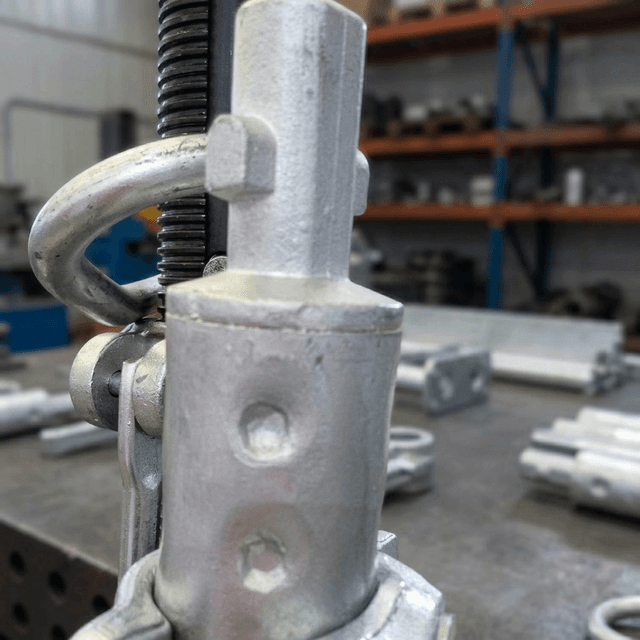
Kwikstage scaffold ties and wall anchors connect the scaffold to a supporting structure and help control lateral movement. For a buyer, the useful question is whether the complete connection matches the project tie duty, substrate and installation conditions. A strong coupler cannot compensate for a weak wall, an unsuitable anchor or an unverified bracket weld. Treat the tie assembly as a specified load path rather than a miscellaneous accessory in the component order.
This guide helps scaffolding contractors, fleet buyers, temporary works coordinators and importers prepare comparable quotations. It explains push-pull restraint, the design questions raised by netting and sheeting, six tie arrangements, anchor-testing responsibilities and an eight-point factory acceptance checklist. The worked calculations are transparent purchasing examples; they are not test results or approved tie layouts.
Scope and review date: November 8, 2026. This is an English-language, global procurement guide. UK NASC guidance and Australian sources are identified individually; their requirements are not interchangeable. The destination jurisdiction, current system manual and competent scaffold designer determine the governing rules. This article does not certify a product, prescribe a universal tie grid or replace a project design and anchor installation procedure.
To coordinate your tie schedule with your primary structure, review your Kwikstage standards, ledgers and transoms, and steel planks. When you are ready to finalize component quantities, visit our commercial inquiry desk for an anchor hardware quotation.
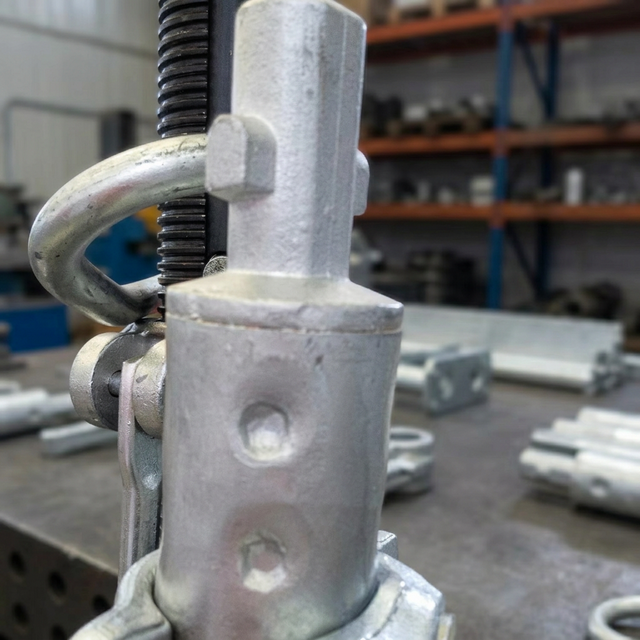
1. The Dual Structural Function of Kwikstage Wall Ties
A tie arrangement has two related jobs: transferring horizontal actions to the building and providing restraint used in the scaffold stability assessment. Identify the whole route from the outer and inner standards through tubes, couplers, brackets and anchors into a suitable structural element. Façade finishes and insulation are not automatically suitable bearing surfaces or anchor base materials.
- Tension and compression: Wind suction can pull a scaffold away from the building; pressure can push it inward. Confirm how each direction is resisted. A ring anchor with a tensile rating does not by itself establish an inward buttress. Ask the designer to identify connection eccentricity, local bearing, tube buckling and whether both lines of standards require restraint.
- Frame stability: Ties, bracing and system joints work together. Removing a tie changes the assumed restraint arrangement even when the weather is calm. Effective buckling length depends on the complete frame and boundary conditions; it cannot be assumed to equal one lift merely because a tie is nearby.
In an ideal Euler column, critical load varies inversely with the square of effective length. That relationship explains why restraint matters, but it does not calculate the remaining capacity of a real Kwikstage scaffold after tie removal. Require an approved replacement arrangement before façade trades interrupt the tie pattern. Record who can authorize a change and how the revised arrangement reaches the erection and inspection teams.
2. Wind Loads: Debris Netting and Sheeting Design Inputs
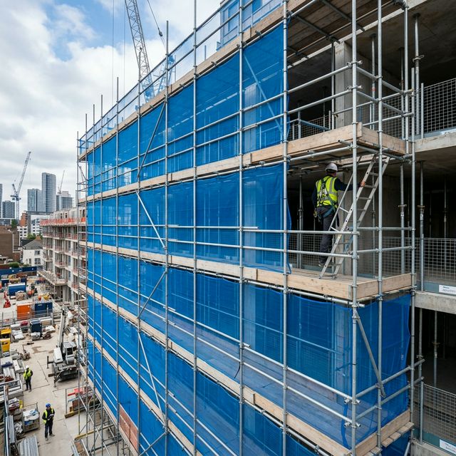
Adding debris netting, shade cloth or solid sheeting changes the exposed surfaces and wind-force assumptions. HSE specifically warns against adding covering without notifying those responsible for scaffold design and erection. An open-scaffold quotation therefore needs a clear exclusion or a covering allowance agreed with the designer; it should not silently assume that any later mesh installation is covered.Read the HSE scaffold design and covering guidance.
Request the covering manufacturer's aerodynamic data, the area and location to be covered, openings and return details, fixing method and intended duration. Shade percentage, visual openness and marketing descriptions such as breathable do not establish a design force coefficient. Site exposure, height, surrounding buildings and local wind rules also matter. Neither a fixed percentage increase nor a standard number of extra ties can be inferred from fabric colour or the words debris netting.
A transparent load-screening example
For an illustrative uniform net design pressure, a tributary-area estimate is F = p_net × A. If a designer supplies p_net = 0.60 kN/m² and an illustrative area A = 12 m², the resulting force is 7.2 kN. At 0.90 kN/m² with the same area, it becomes 10.8 kN, a 50% increase. These are hypothetical inputs, not code coefficients, measured fabric results or a recommended tie spacing.
This arithmetic only screens a purchasing assumption. Real tie reactions depend on frame load distribution, corners, shielding, load combinations and the approved arrangement. Ask for the design tension and compression at the connection and the basis of the declared resistance. Do not compare an unfactored catalogue value with a factored design action unless the designer confirms that the comparison is valid.
3. Kwikstage Tie Hardware Taxonomy: Six Anchoring Methods Compared
Different structural facades, masonry types, and architectural finishes demand different tie configurations. The table below details the six arrangements that may be considered for Kwikstage scaffolding, their load paths and the evidence needed before purchase. Suitability depends on the exact system instructions and project design. The mechanism descriptions below explain load paths and evidence needs:
| Tie Method | Primary Load Mechanism | Compression Load Path | Tension Load Path | Capacity Evidence Required | Substrate Requirement | Critical Failure Risk |
|---|---|---|---|---|---|---|
| Kwikstage Wall Tie Bracket | Designed plate bracket bolted to substrate; specified half-coupler connected to the standard. | Load path: bracket plate bears directly against face of concrete. | Load path: resisted by anchor bolt tension and coupler slip resistance. | Declared assembly tension and compression capacities, including welds. | Solid reinforced concrete slab edge, precast beam, or solid brickwork. | Concrete edge breakout; check the anchor approval for edge distance, spacing and member thickness. |
| Anchor Tube & Right-Angle Couplers | 48.3 mm steel tube clamped to both inner/outer standards via Class B right-angle couplers; bolted to wall via eye-bolt or ring-anchor. | Load path: steel tube buttressed against building surface or reveal pad. | Load path: direct tensile pull on anchor ring bolt and coupler jaw. | Verify tube, coupler, anchor and buttress as an assembly; a second coupler does not automatically double resistance. | Suitable structural base material; anchor selection and any steel connection need separate details. | Coupler slip or tube damage if tightening differs from the exact product instructions. |
| Lip Tie / Slab Clamp | Hooked tube or dual-coupler assembly clamped over reinforced concrete slab edge or parapet wall. | Load path: positive bearing against interior or exterior slab face. | Load path: dependent on hook geometry and secondary clamping. | Model-specific clamp rating, permitted geometry and supporting member check. | Structural slab or upstand verified for local bearing and the applied reactions. | Parapet overturn if masonry parapet lacks tie-down reinforcement. |
| Column Box Tie | Tube frame around a concrete or steel building column, with connections and packing defined by the approved detail. | Load path: direct mechanical bearing against column face via timber packing. | Load path: positive mechanical interlock behind opposite column face. | Design check for tube bending, couplers, packing and column reactions. | Isolated structural columns or internal lift cores. | Loose packing timbers vibrating free over time; requires wedging checks. |
| Through-Tie (Window Opening Yoke) | Internal cross-tube spanning across internal window reveal, clamped to exterior scaffold tie tube. | Load path: exterior tube bears against outside wall face. | Load path: internal bridle tube bears against inside wall face. | Design check for the yoke, connections and local bearing at the opening. | Window or doorway structural openings in load-bearing masonry/concrete. | Glass or frame damage if timber protection pads are omitted; window trade obstruction. |
| Reveal Tie (Friction Screw Jack) | Adjustable screw jack compressed between window reveals with timber spreaders; tie tube clamped at 90°. | Load path: dependent on friction preload and reveal rigidity. | Load path: strictly friction-based; vulnerable to thermal contraction and vibration. | Explicit project approval, rated friction arrangement and inspection plan. | Solid masonry or concrete reveals only (never drywall or lightweight AAC blocks). | Loss of friction or preload; do not assume approval for a netted or sheeted scaffold. |
For general hire fleets and high-rise contracting, the Kwikstage Wall Tie Bracket (single or double half-coupler) combined with a suitable mechanical or bonded anchor can offer a repeatable installation process where the substrate and system permit it. Where drilling into the building face is prohibited by architectural specifications (such as restoration masonry or glass curtain walls), temporary works engineers may consider arrangements such as Column Box Ties and Through-Ties, with the designer explicitly deciding whether any friction reveal ties are permissible.
4. Tie Patterns: Six Scenarios to Resolve Before Ordering
A tie grid belongs to a defined scaffold configuration. Obtain a marked elevation showing horizontal and vertical locations, tie duties, edge details and any restrictions imposed by the building owner. Record the applicable system manual or design reference and revision. The following matrix turns common configuration changes into questions for the designer and supplier; it deliberately provides no universal spacing.
| Configuration | Design information needed | Purchasing decision |
|---|---|---|
| Open scaffold within system guidance | Confirm height, bay and lift geometry, exposure and permissible tie positions. | Order the exact scheduled arrangement; retain the system reference with the BOM. |
| Open scaffold at an exposed site | Provide site location, elevation and local wind-design basis. | Resolve any change in tie duty or anchor selection before comparing prices. |
| Partially netted elevation | Identify fabric product, coverage zones, openings and aerodynamic evidence. | Separate quantities by zone; do not apply a whole-elevation average blindly. |
| Fully netted or shade-cloth covering | Obtain product-specific wind inputs and the approved covering arrangement. | Request a revised tie schedule and any additional hardware as separate lines. |
| Solid sheeting or containment | Define sealed areas, returns, access openings and erection stages. | Use the approved design reactions to select the complete connection. |
| No-drill façade or restricted tie locations | Map accessible structural columns, openings and prohibited fixing zones. | Price approved box or through-ties and access constraints before substituting anchors. |
Connection position matters: use the permitted offset from system nodes stated in the current manual or project design. Moving a bracket along a standard can change eccentricity and local bending. A convenient installation position is not evidence of adequate capacity. If the scheduled node is obstructed, obtain a revised detail rather than treating a generic distance as permission to relocate it.
At this stage, send the marked tie elevation, substrate description and destination market to the commercial inquiry desk for a component and documentation quotation. Identify unresolved design items in the inquiry so that an allowance is not mistaken for an approved substitution.
5. Anchor Proof Testing: NASC Guidance and Local Boundaries
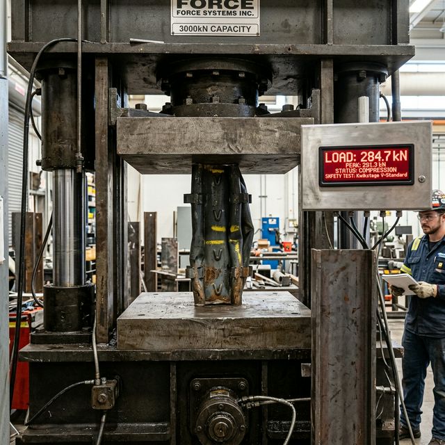
Distinguish laboratory component testing from testing a fixing in the actual building. Neither a coupler certificate nor a compression test establishes pull-out resistance in old brickwork. The testing plan should identify the responsible person, equipment, locations, acceptance criteria, reporting method and action on failure before erection begins.
A. Preliminary assessment and installation proof tests
The NASC TG4:25 public summary distinguishes preliminary checks of an uncertain anchor/base-material combination from proof checks of installed anchors. Preliminary test anchors are not subsequently used. For proof testing, it specifies at least 5% of anchors, randomly selected, with at least three in each separate and distinct area, at 25% above the specified tie duty. This is UK guidance, not a universal Australian or global test rule.
B. Applying the stated factor without confusing ratings
For an illustrative design tie duty of 4.0 kN, multiplying by 1.25 gives a 5.0 kN proof-test target. This arithmetic does not select an anchor or establish its working capacity. Record the project tie duty and authorized test target separately from the component catalogue rating. The full applicable procedure must define the load application, hold period, movement criteria and suitable reaction arrangement.
C. Traceable records and action on failure
Keep an elevation map of tested positions, anchor model and batch, substrate description, installer, test date, equipment calibration reference and observed results. Where an anchor fails, isolate the affected work and refer the finding to the responsible designer and testing lead for investigation and the required expanded testing or remedial design. Do not improvise a reduced duty or a sample escalation rule from this purchasing guide.
Outside the UK, agree the applicable local standard and project procedure explicitly. Australian buyers can use the Safe Work Australia general guide as risk-management context and confirm requirements with the relevant jurisdiction. A guide, a standard and enforceable local rules have different roles; this article does not treat them as equivalent.
6. Factory Quality Control & Sourcing Checklist for Importers
Make acceptance criteria part of the purchase order. A product described as heavy duty or compatible may still differ in geometry, installation torque and declared resistance. Agree which records apply to the exact supplied assembly and which inspections will be performed before the goods leave the factory. Use this checklist to compare evidence rather than imposing unsupported dimensions on every supplier's design.
8-Point Factory Quality Acceptance Checklist: Kwikstage Wall Ties
- Drawing and material identity: obtain the approved drawing revision, steel specification, plate thickness and allowed tolerances. Check supplied measurements against that drawing; neither a nominal 10 mm plate nor a grade name alone proves duty.
- Coupler and assembly evidence: identify the exact coupler model, tube compatibility and declared standard. Obtain evidence covering its use in the bracket assembly, including tension and compression; a standalone coupler report is insufficient.
- Weld requirements: agree joint geometry, weld size, inspection method and acceptance criteria from the approved design. Request procedure and inspection records linked to the supplied batch. Surface appearance cannot establish penetration or capacity.
- Fasteners and installation instructions: verify bolt and nut identity, thread condition and specified tightening procedure. Record the manufacturer's torque and tool requirements; do not substitute a generic torque because the nut looks familiar.
- Anchor interface: compare bracket holes, washers, standoff and bearing faces with the selected anchor detail. Check substrate edge distance, embedment and member thickness separately; plate-edge clearance does not establish concrete-edge clearance.
- Coating and moving parts: agree the coating specification and inspection plan for the product and environment. Check coated threads, hinge movement and contact surfaces. Coating thickness acceptance depends on the applicable product specification.
- Fit-up and packing: compare an identified sample with the intended standard and connection detail. Check clearance, flap engagement and packing protection. A successful fit-up records dimensional compatibility, not a structural load test.
- Traceability and release documents: require material records, component markings, inspection results and packing labels that connect the shipment to a production batch. Agree document type, language, inspection scope and any independent witness before paying for requirements that were never included in the quotation.
7. Commercial Estimating: Estimating Tie Bill of Materials (BOM)
The following is a hypothetical quantity worksheet for a 50 m × 20 m elevation, or 1,000 m². The assumed areas per tie are independent estimating inputs, not approved grids or recommendations for particular coverings. Calculate N = ceiling(elevation area / assumed area per tie), then add an explicitly chosen 10% purchasing spare allowance, rounded up. The installed schedule still needs individual tie positions and edge details.
| Estimating scenario | Assumed area per tie | Base count N | Brackets with 10% spares | Anchors, if one per bracket |
|---|---|---|---|---|
| Example A | 24 m² | 42 | 47 | 47 |
| Example B | 14 m² | 72 | 80 | 80 |
| Example C | 8 m² | 125 | 138 | 138 |
For Example B, ceiling(1,000 / 14) = 72 and ceiling(72 × 1.10) = 80. The 80 purchased brackets include eight spares; spares do not replace required installed ties. The one-anchor-per-bracket assumption is only for the worksheet. A two-anchor bracket would require 160 anchors for those 80 assemblies, subject to its actual detail and the testing plan. Tubes, couplers, washers and other parts must be counted from the chosen assembly rather than inferred from bracket quantity.
Use the designer's issued tie schedule for the final order and separate production anchors, preliminary test anchors and purchasing spares. Compare quotations on the same assembly, documentation package, inspection scope, packing method and delivery basis. A lower unit price may exclude anchors, test records or site testing; ask for those items as separate lines so the landed procurement comparison remains useful.
Request a Documented Kwikstage Tie Hardware Quotation
Send your destination market, system reference, marked tie schedule, design duties, substrate and required documents to Kwikstage Direct. Ask the commercial team to confirm component availability, evidence, inspection scope and delivery terms for the quoted batch. Technical suitability and any substitutions remain subject to project approval.
8. Frequently Asked Questions (FAQ)
- What is the safe working load of a Kwikstage wall tie bracket?
- There is no universal rating for a Kwikstage wall tie bracket. Obtain the declared tension and compression capacities for the exact bracket, coupler, anchor and substrate arrangement. A coupler test value alone does not rate the assembled connection, and adding a second coupler does not automatically double its capacity.
- Does debris netting require a different scaffold tie pattern?
- Netting or sheeting changes the wind-loading assumptions and requires design review before installation. Ask for fabric aerodynamic data and a revised tie schedule. Shade percentage is not a wind-force coefficient, and no fixed spacing or load multiplier applies to every mesh and site.
- What is the difference between a tension tie and a push-pull tie?
- A tension tie resists outward movement. A push-pull arrangement also provides an inward compression load path. The design must establish both directional demands and capacities, including bearing, tube buckling, bracket eccentricity and the connection to the building. The two directional ratings need not be equal.
- Which anchor proof-test factor does the NASC TG4:25 summary specify?
- The NASC public summary specifies a proof load 25% above the project tie duty. Section 5 links the source and separates this UK guidance from the testing plan required in other jurisdictions.
- Can reveal ties replace drilled anchors on a Kwikstage scaffold?
- Reveal ties depend on friction, preload and the condition of the opening. Accept them only where the system instructions and project design permit the specific arrangement, with inspection and any supplementary restraint defined. Do not assume a universal percentage allowance or substitute them when drilling is prohibited.
- What should an importer request before ordering wall tie brackets?
- Request a revision-controlled drawing, exact component identities, complete-assembly capacity evidence, installation instructions, material and weld records, coating requirements and batch traceability. Specify the destination market and anchor substrate separately. Agree which documents and inspections are included in the quotation before placing the purchase order.
9. Sources & Verification Limits
Sources checked on November 8, 2026. These public guidance pages support the stated management and testing context. Full standards, manufacturer manuals and project-specific anchor approvals have not been reviewed here. The worked examples are editorial calculations, and the images are illustrative library assets. Verify the current governing documents and destination requirements before selecting or installing components.
- NASC — TG04:25 Anchorage Systems for Scaffolding, public summary. Source for the UK preliminary/proof-test distinction, sampling and proof-load factor in Section 5; obtain the full procedure for use.
- HSE — Scaffolds. UK guidance on system instructions, design, ties and covering. This web page is not the separate HSG150 publication.
- Safe Work Australia — General guide for scaffolds and scaffolding work. Australian risk-management guidance, not a Code of Practice or verification of a specific Kwikstage product.
To review related component specifications, return to the Kwikstage buyer insights index or explore our complete modular scaffold packages.